The battery gets a charge in the car from the generator while the vehicle is moving. However, as a safety element, an electrical circuit includes a control relay that provides the output voltage from the generator at 14 ± 0.3 V.
Since it is known that a sufficient level for full and fast charging of the battery should be at 14.5 V, it is obvious that the battery will need help to fill the entire capacity. In this case, you need to either store the device, or you need to make a charger for a car battery with your own hands at home.
Content
- 1 Features of battery charging
- 2 Circuit diagram on capacitors
- 3 Current limiter
- 4 Protection against incorrect polarity in the charger
- 5 Automatic for homemade charging
- 6 Charger layout
- 7 Constituent elements
- 7.1 Printed circuit board
- 7.2 Graduation scale
- 7.3 Connecting cables
- 7.4 Electric homemade charging elements for batteries
- 8 Setup and Startup
Features of battery charging
In the warm season, even a half-discharged car battery will allow you to start the engine. During frost the situation is worse, because at negative temperatures the capacity decreases, and at the same time the starting currents increase. By increasing the viscosity of cold oil, more effort is required to crank the crankshaft. This means that during the cold season, the battery needs a maximum charge.
A large number of various options for homemade chargers allows you to choose a scheme for different levels of knowledge and skill of the manufacturer. There is even an option in which the car battery charger is made using a powerful diode and an electric heater. A two-kilowatt heater, included in a 220 V household network, in a series circuit with a diode and a battery will give the last a little more than 4 amps of current. During the night, the scheme will “wind up” 15 kW, but the battery will receive a full charge. Although the overall efficiency of the system is unlikely to exceed 1%.
Those who are going to make a simple battery charger with their own hands with transistors should know that such devices can overheat significantly. They also have problems with incorrect polarity and accidental short circuit.
For thyristor and triac circuits, the main problems are charge stability and noise. Radio interference, which can be eliminated with a ferrite filter, and problems with polarity are also negative.
Quite a few can be found suggestions for the alteration of a computer power supply in a self-made charger for the battery. But you need to know that although the structural diagrams of these devices are similar, but the electrical ones have significant differences. For the correct alteration, you will need sufficient experience in working with schemes. Not always blind copying with such alterations leads to the specified result.
Circuit diagram on capacitors
The most interesting may be the capacitor circuit of a home-made car charger. It has a high efficiency, does not overheat, provides a stable current, despite the level of battery charge and possible problems with network fluctuations, as well as withstand short-term short circuits.
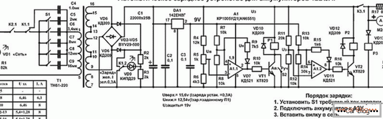
Visually, the picture seems too cumbersome, but with a detailed analysis of all areas become clear. It is even equipped with a shutdown algorithm when fully charged.
Current limiter
For capacitor charging, the regulation of the strength of the currents and its stability is ensured by the series connection of the transformer winding with ballast capacitors. In this case, there is a direct relationship between the charging current of the battery and the capacitance of the capacitors. Increasing the latter, we get more amperage.
Theoretically, this scheme can already work as a battery, but the problem will be in its reliability. Weak contact with the battery electrodes will destroy unprotected transformers and capacitors.
See also: DIY car battery maintenance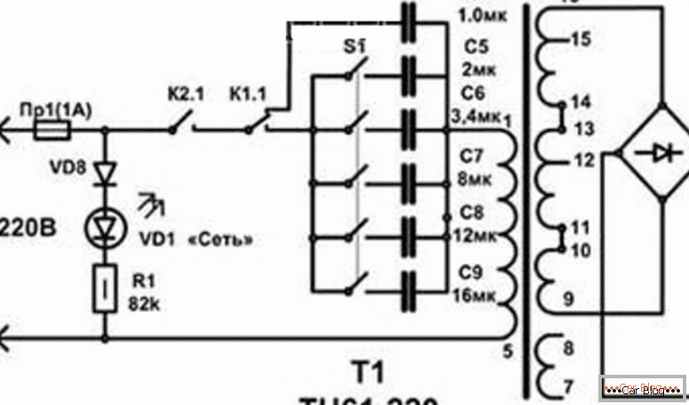
Any student studying physics will be able to calculate the required capacitance for capacitors C = 1 / (2πvU). However, it will be faster to do this using a previously prepared table:
| Capacitor Selection Table | ||||||||||
| Battery charge current, A | 0,5 | 1,0 | 2,0 | 3,0 | 4,0 | 5,0 | 6,0 | 7,0 | 8,0 | 9,0 |
| Capacitor value, microfarad | 1,0 | 3,4 | 8,0 | 12,0 | 16,0 | 20,0 | 24,0 | 28,0 | 32,0 | 36,0 |
In the circuit can reduce the number of capacitors. To do this, they are connected in groups or using switches (toggle switches).
Protection against incorrect polarity in the charger
In order to avoid problems when reversing the contacts, there is a relay P3 in the circuit. Incorrectly connected wires will protect the diode VD13. He will not let the current in the wrong direction and will not close the contact K3.1, respectively, the wrong charge on the battery will not work.
If the polarity is observed, the relay closes and charging starts. This scheme can be used on any of the types of self-made charging devices, even with thyristors, even with transistors.
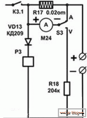
Switch S3 controls the voltage in the circuit. The lower circuit gives the value of the voltage (V), and with the upper connection of the contacts we get the level of current (A). If the device is connected only to the battery without being connected to the home network, then you can find out the battery voltage in the corresponding position of the switch. The head is an M24 microammeter.
Automation for homemade charging
As the power amplifier select the nine-volt scheme 142EN8G. This choice is based on its characteristics. After all, with temperature fluctuations of the board's case even by ten degrees, at the output of the device, voltage fluctuations are reduced to errors in hundredths of a volt.
The disconnection is triggered at a voltage parameter of 15.5 V. This part of the circuit is labeled A1.1. The fourth pin of the microcircuit (4) is connected to the divider R8, R7 where a voltage of 4.5 V. goes to it. Another divider is connected to the resistors R4-R5-R6. As a setting for this circuit, an adjustment of resistor R5 is used to indicate the level of excess. With the help of R9 in the chip, the lower level of switching on the device is controlled, which is carried out at 12.5 V. Resistor R9 and diode VD7 provide a voltage interval for uninterrupted charging.
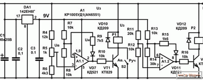
The algorithm of the scheme is quite simple. Connecting with the charger, the voltage level is monitored. If it is below 16.5 V, then the circuit passes the command to open the transistor VT1, which, in turn, starts the connection of the relay P1. After that, the primary winding of the installed transformer is connected, and the process of charging the battery is started.
After dialing the full capacitance and obtaining the output voltage parameter at the level of 16.5 V, the voltage in the circuit is reduced in order to keep the transistor VT1 open. Relay conducts shutdown. The feed to the terminals of the current is reduced to the level of a half ampere. The charging cycle is restarted only after the voltage on the battery terminals has decreased to 12.5 V, then the charging supply is resumed.
So the machine controls the ability not to recharge the battery. The scheme can be left in working condition even for several months. This option will be especially relevant for those who use the car seasonally.
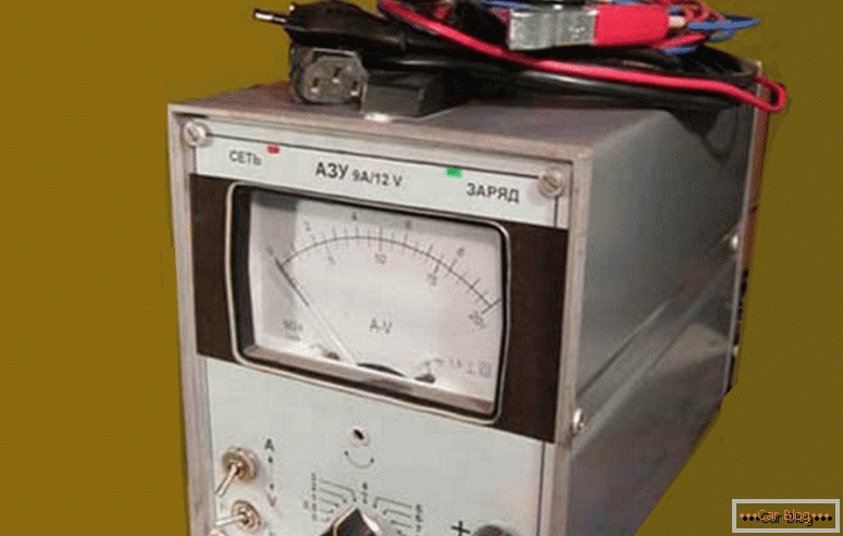
Charger layout
The case of such a device can serve as a milliammeter VZ-38. Unnecessary interiors are removed, leaving only an arrow indicator. We mount everything except for the automatic machine mounted method.
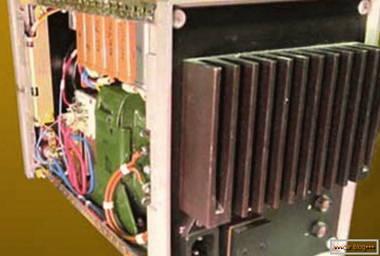
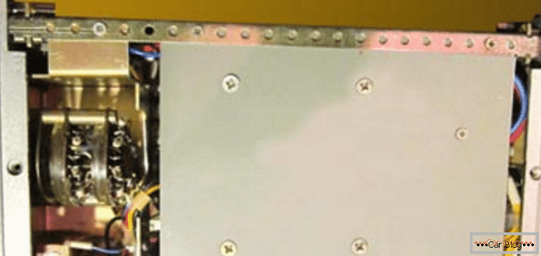
The appliance consists of a pair of flaps (front and back), which are fixed with perforated horizontal coal beams. Through these holes it is convenient to mount any structural elements. For the location of the power transformer used a two-millimeter aluminum plate. It is fastened with screws to the bottom of the device.
See also: Types and designation of car lamp caps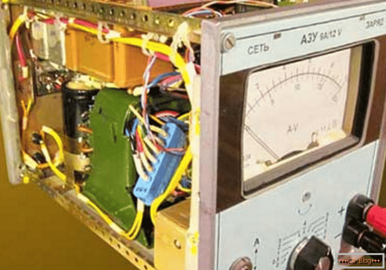
On the upper plane a fiberglass plate with a relay and capacitors is mounted. On the perforated ribs also fixed board with automatics. The relays and capacitors of this element are connected using a standard connector.
To reduce the heating of the diodes will help the radiator on the back wall. In this area it is appropriate to place the fuses and a powerful plug. It can be taken from the power of the computer. To clamp the power diodes use two clamping strips. Their use will allow rational use of space and reduce heat generation inside the unit.
It is advisable to carry out the installation using the intuitive colors of the wire. We take red as positive, blue for negative, and select alternating voltage with, for example, brown. The cross section in all cases should be more than 1 mm.
The readings of the ammeter are calibrated with a shunt. One of its ends is soldered to the contact of the relay P3, and the other is soldered to the output terminal of the plus.
Constituent elements
Let us examine the insides of the device, which form the basis of the charger.
Printed circuit board
Steklotekstolit is the basis for the PCB, which serves as protection against voltage surges and connection problems. The image is formed in 2.5 mm increments. Without special problems this scheme can be made in living conditions.
-
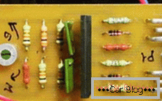
- Location of elements in reality
-
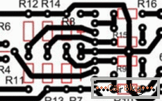
- Soldering Layout
-
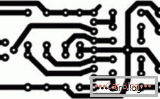
- Manual soldering board
There is even a schematic plan with highlighted elements on it. A clean image is used to apply it to the substrate using powder printing on laser printers. For the manual method of applying tracks fit another image.
Graduation scale
The indication of the installed milliammeter VZ-38 does not correspond to the real readings that the device gives out. To adjust and correct the calibration, it is necessary to glue a new scale to the base of the indicator behind the arrow.
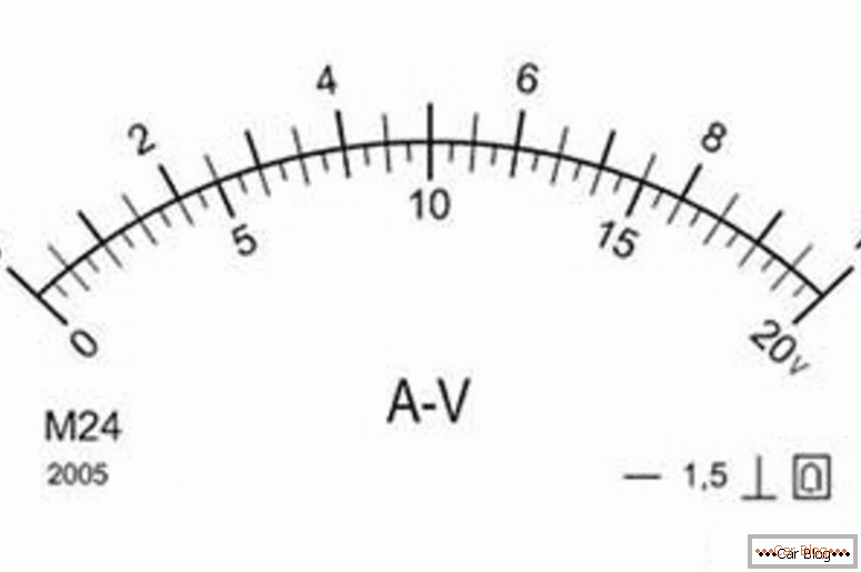
The updated information will be accurate to 0.2 V.
Connecting cables
The contacts that will be connected to the battery must have a spring clip with prongs (“crocodile”) at the ends. To distinguish between the poles, it is desirable to immediately select the positive part in red, and take the negative cable with the clip blue or black.
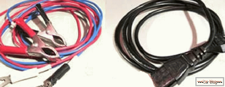
The cable cross section must be more than 1 mm. To connect to the household network, a standard non-separable cable with a plug from any old office equipment is used.
Electric elements homemade charging for battery
The TN 61-220 will be suitable as a power transformer, because the output current will be at 6 A. For capacitors, the voltage must be more than 350 V. We use the MBGC type for capacitors from C4 to C9. Diodes from the 2nd to the 5th are needed to withstand a ten-amp current. The 11th and 7th can take any impulse. VD1 is an LED, and the 9th may be an analogue of KIPD29.
For the rest, you need to focus on the input parameter, which allows a current of 1A. In the relay P1, you can use two LEDs with different color characteristics, and you can use a binary LED.

The operational amplifier AN6551 can be replaced by the domestic analogue KR1005UD1. They can be found in old sound amplifiers. The first and second relays are selected from a range of 9–12 V and a current of 1 A. For several contact groups in the relay device, we use paralleling.
Setup and Startup
If everything is done without errors, then the scheme will work immediately. Adjust the threshold voltage using a resistor R5. It will help to transfer charging to the correct mode of low currents.
For the provided schemes we thank the site ydoma.info.


