Today, automotive products are high-tech and fast. Therefore, for better braking on all modern cars, both Russian and imported, use a vacuum brake booster. The rapid productivity and productivity is explained by the fact that the improved brake system simplifies the control of the vehicle, giving a slight pressure on the pedal to stop the transport. Without this knot, with one physical force, developing all the power for good braking is not easy, because after a while fatigue will appear. Thus, VUT is designed to minimize the effort in time of pressing on the brake pedal during any types of braking.
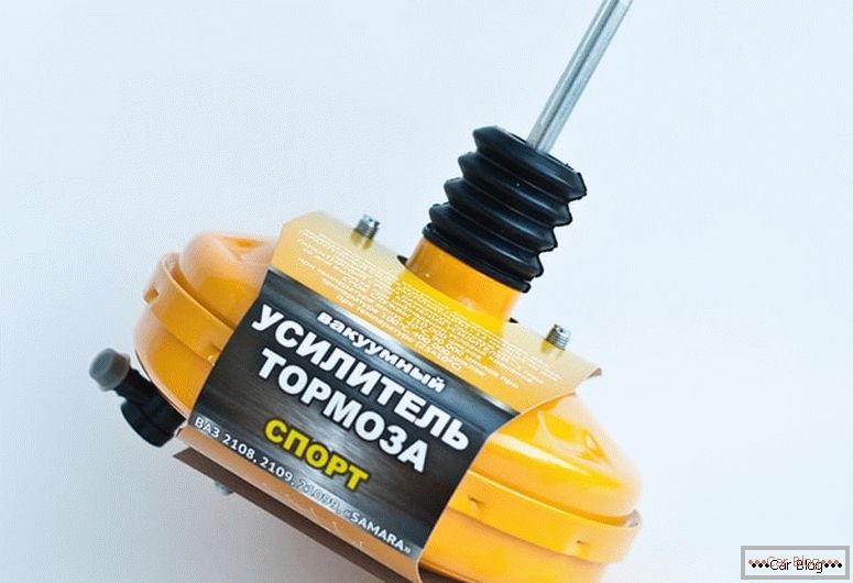
Vacuum brake booster
The principle of operation of the vacuum brake booster основан на воздействии внешнего атмосферного давления на разряженную область. Хоть стандартной схемы устройства и конструкции усилителей нет, но принцип работы остается неизменным. Есть масса конструктивных решений и модификаций, отличных друг от друга деталями, а также конфигурацией. Так, в ряде транспортных средств может крепиться дополнительный вакуумный электромотор, отвечающий за слаженную работу узла при различных условиях функционирования двигателя. Если говорить о дизельных силовых агрегатах, то в них приспособление идет в обязательном порядке.
Content
- 1 VUT device
- 2 How does VUT work?
- 3 Signs of problems VUT
- 4 Troubleshooting methods
- 5 Leak test
- 6 Freewheel adjustment
- 7 Pressure control lever adjustment
- 8 Removal of VUT, if repair is required
- 9 Instructions for replacing the brake servo
VUT device
This node consists of five unchanged components:
- separating diaphragm from plastic material;
- return spring;
- pedal pusher;
- stock;
- valve gear.
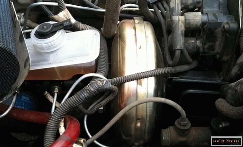
At first glance, the vakuumnik in the engine compartment is invisible, as it is located in a monolithic block with the SEC between the pedal mechanism and the brake master cylinder. It is a camera delimited by a diaphragm-type partition. The divided cavities are hermetic and equal. One side of the cavity is connected to the atmosphere, and the other to the pipe of the exhaust manifold of the motor, where during operation there is a low pressure than in the atmosphere.
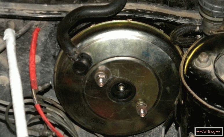
Location VUT
Атмосферная часть расположена ближе к педали, а вакуумная размещается возле цилиндра. В задней атмосферном отсеке на корпусе имеется обратный клапан, который задерживает разрежение во всасывающей трубе двигателя и препятствует попаданию бензиновой смеси в узел. Степень разрежения в этой камере регулируется именно клапанным следящим механизмом. А в передней полости обратный клапан держит постоянное напряжение. Так, на перегородку с двух сторон давит одинаковое по значению давление. Сам клапан перемещается посредством толкателя, соединенного с педалью тормоза. Возвратная пружина отвечает за возвращение в исходное состояние диафрагмы после торможения. Когда машина требует наличия системы экстренного торможения, то на stock матируется специальный электромагнитный привод.
The device of the vacuum brake booster is not complicated, which makes it possible to carry out repair work with his own hands.
How does VUT work?
Работа устройства осуществляется за счет разности давления, образующегося в вакуумном и атмосферном отсеке. Из-за этого перепада приводится в действие толкатель, который и двигает stock поршня ГТЦ. Рассмотрим подробно, как работает вакуумный усилитель тормозов. Изначально, давление в обеих камерах одинаково.
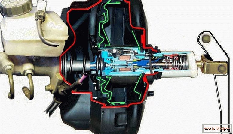
VUT device in section
Передача усилия к толкателю и последующим элементам происходит, когда водитель воздействует на педаль тормоза. После того как усилие доходит до клапана, он закрывает проход между обоими отсеками. Потом клапан опять соединяет обе камеры и уже в атмосферном отсеке происходит понижение давления. Возникшая разница отражается на перегородке, отчего она выгибается и ведет к движению stockа поршня в ГТЦ. Когда автомобиль заканчивает торможение давление в обоих отсеках выравнивается, а эластичная перегородка принимает начальное положение.
Выход ВУТ из строя является серьёзной проблемой, способной привести к фатальным последствиям. Чтобы этого избежать, нужно внимательно следить за тормозной системой. Малейшее отклонение в работе обязывает провести диагностику. Adjusting the vacuum brake booster занятие несложное, исправить некоторые отклонения возможно самостоятельно.
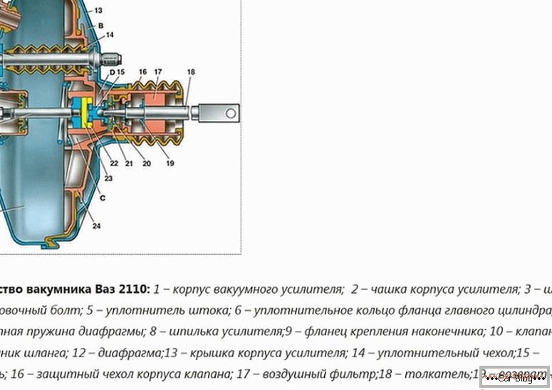
Components of the vacuum brake booster
Signs of problems VUT
Vacuum brake booster способен как частично не создавать вакуум, так и полностью. Основной причиной этому может быть обрыв или разгерметизация соединительных трубок моторного коллектора и усилителя. Кроме того неполадки могут быть вызваны и из-за нарушения целостности или потери эластичности диафрагмы. Если в механизме случился сбой, это заметит даже новичок. Перечислим основные признаки неисправности вакуумного усилителя тормозов:
- with pressure on the brake pedal, you need to make an effort, which should not be;
- extraneous noise in the system. Sounds appear due to depressurization and rupture of the hose;
- VUT draws air;
- there are smudges on the "vakuumnik";
- wear of oil seals, rupture of diaphragm or rubber on valves;
- at idle speed, the motor behaves evenly and rhythmically like a clock; this is due to the fact that during depressurization, excess air is drawn in and mixed with the fuel mixture.
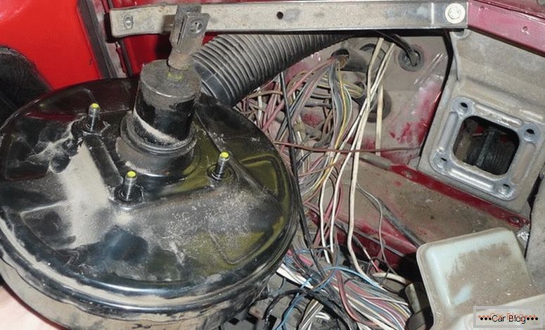
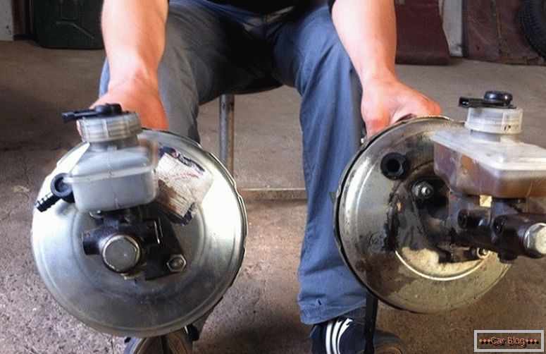
Removed faulty amplifier
Troubleshooting methods
For those who are wondering how to check the vacuum brake booster, we have given several options for the initial verification of the system. The performance of HLA is checked in the following ways:
- The brake pedal is pressed and the engine starts. There is a strong pushing of the pedal, if it has not returned to its former position, it means that the node has problems exactly.
- The engine starts, it takes a few minutes, it is jammed. Then several times, without straining, they press on the brake pedal. If everything is in order, then after the first onset, the pedal is squeezed out, as required, until it stops. This suggests that the resulting vacuum pulled the septum, and the rod began to push, as it should be the GTZ piston. But if during the second pressing of the pedal, the stroke will decrease, it means that there is no place to take the discharge. When after the first press no further action is felt, then the system is faulty.
- This test method can detect air leaks in the system. At the started engine the pedal chokes and is late. Without releasing the brake, the motor is muffled; in this position, the pedal should be held for thirty seconds. If there is a pedal movement, it means that the tightness is somewhere broken. In the chamber, the pressure and diaphragm will begin to increase, and under the pressure of the return spring, the plunger will act. When during such a test the pedal remains unchanged, it means that VUT is working properly.
- It is also possible to check the air leak in a similar way: with the engine off, repeatedly press the pedal until it stops, and then, while holding the pedal, start the engine. By means of temperature changes in the chambers, the pedal should come down slightly. When this did not happen, then you need to proceed to check the integrity of the hoses themselves. In the event that after the elimination of “air leaks” the system continued to “troit”, then it is time to replace the amplifier with a new one.
If, after the initial check, malfunctions were noticed, then it is necessary to proceed to a longer process — inspection for the integrity of the parts.
Diagnosis of VUT
Leak test
Inspection steps:
- Open the hood of the car, and turn on the engine for two minutes.
- After mute, wait half a minute.
- Press the brake pedal several times and it should be heard as air enters the system.
- At the same time pay attention to the check valve VUT. To do this, remove the checked part from the rubber seal of the flange.
- Put a suitable rubber bulb on the small fitting, you can take it from the hydrometer.
- Next, squeeze it when the valve is in order, the rubber bulb will not open. If this happens, you should replace the valve itself and check the vacuum brake booster again. If nothing has changed and the problems are also noticeable, then the problem is in the system itself, which is easier to change than to repair yourself. Without proper knowledge and tools, self-repair is impossible.
If you have meters, you can check for tightness under load. To do this, start the engine, and then press the brake pedal under a force of 20 kG. Hold the pedal until the vacuum in the VUT reaches the point B = 66.7 kPa (500 mmHg). After you stop the motor and check the output of the vacuum gauge, - the rate of reduction of the vacuum should not exceed 3.3 kPa for 15 s. When your readings are different, you need to repair or replace the amplifier.
Leak test
And also it is possible to check the system with a meter and without load. To do this, start the motor, do not depress the brake pedal at this time, and wait until the depth of discharge is equal to A = 66.7 kPa (500 mmHg. Art.). After you stop the engine, compare the data of the vacuum gauge. Its speed of reducing the depth of discharge should be no higher. 3.3 kPa in 15 seconds. If a discrepancy is found, look for and correct the cause of the leakage.
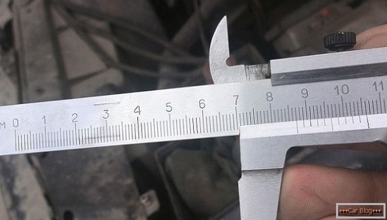
Freewheel adjustment
After a leak test, it is worth adjusting the brake pedal free play. Adjusting the length of the rod leads to a gap that determines the degree of pressure on the brake cylinder. It is important to properly adjust the length of the rod and set the appropriate clearance. When the engine is not running, the pedal free stroke must be equal to 5-14 mm. This gap is controlled by a bolt located above the VUT plane. When the gap is small, then there is a jamming of the working cylinder, and this leads to accelerated wear of the pads and increased fuel consumption. And also the car will begin to brake arbitrarily, and remind driving a handbrake. On the contrary, the gap exceeded the permissible norm indicates a violation of tightness in the knot and the stroke at the pedal will become increased.
Adjusting the pressure lever pressure
Hydraulic pressure can also be checked with gauges. When the engine is not started, the depth of discharge will be 0 mmHg. st. And if you will squeeze the pedal, with a force of 20 kgf, then the pressure should rise to 1177 kPa (12 kgf / cm2). Now we start the engine and wait until the depth of discharge decreases to 66.7 kPa (500 mmHg. Art.), then look at the parameters of the pressure gauge. Its normal value should be 6867 kPa (70 kgf / cm2).
Simple stroke adjustment
If there are no measuring devices at hand, the test is carried out as follows:
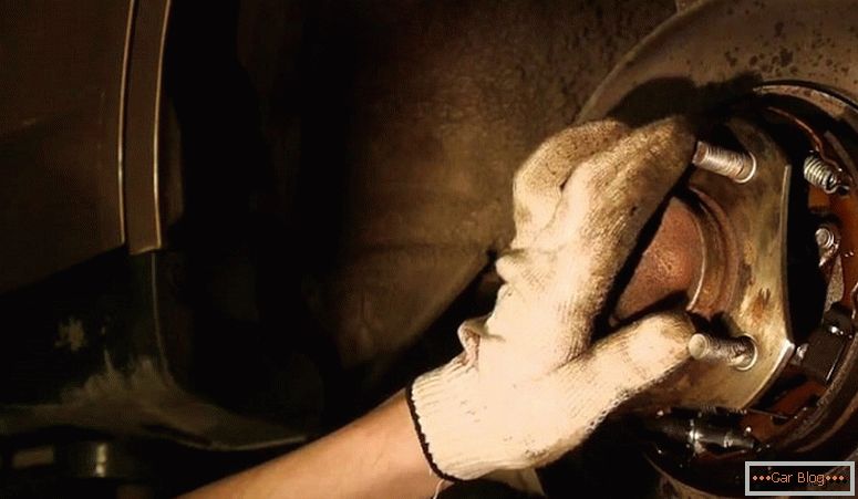
- Look at the details of the drive and the regulator on the state, there should be no gaps and oil spills on them.
- Press the brake and check how far the piston of the regulator extends. The norm is 1.7–2.3 mm. If the course is too high or, on the contrary, it is absent, then there are problems in the regulator.
- Check the test plug, it should be sunk in the body gap up to the stop and there should not be any leaks of brake fluid on it. If everything is different, then the tightness of the sealing cuffs is broken. In such a situation, a complete replacement of the regulator is required.
It is necessary to carry out diagnostics and adjustment of the lever often. When the problem is obvious, the adjustment is as follows:
- Put the car on level ground.
- The lock nut of the bolt is loosened by turning it 3 turns and turning it up to connecting with the regulator piston tail.
- Twist the bolt itself on the appropriate number of your brand faces.
- Next, tighten the nut and watch the piston move, its rate is 1.7–2.3 mm.
- After a complete check is carried out on the move in dry weather. While driving, you need to brake until the wheels are locked. If the drive is adjusted, right, then there should be an advance in locking the front wheels relative to the rear ones. If everything is different, then the bolt dragged. It should be weakened by 1-2 facets and then re-tested in dynamics.
Replacing the brake servo
Removal of VUT, if repair is required
When, after diagnostics, you find that the amplifier needs repair, and you clearly, you know, its structure, as well as all the mechanics of working with it, you can proceed to removing the device:
- First you need to get a repair kit.
- Familiarize yourself with the manual of your car in order to know exactly the design of HLA.
- If there is an upholstery in the engine compartment, and a plastic lining that protects the car, we remove them.
- Under the steering shaft we disconnect the drive of the amplifier from the brake pedal.
- The key 17 unscrew the device from the brake cylinder. Next, remove the tube from the nozzle so that the hose does not turn out to bend, slightly tilt the brake cylinder forward.
- We remove the wire stop signal, and then the key to 13 remove the bolts to release the VUT. For successful removal, we pull out the finger connecting the amplifier and the pedal. After that, remove the two nuts on the bracket mounting.
- Now proceed to repair vakuumnika.
It is worth understanding if you are unable to carry out repairs yourself, it is better to entrust this business to an experienced mechanic or simply to replace it with a new device.
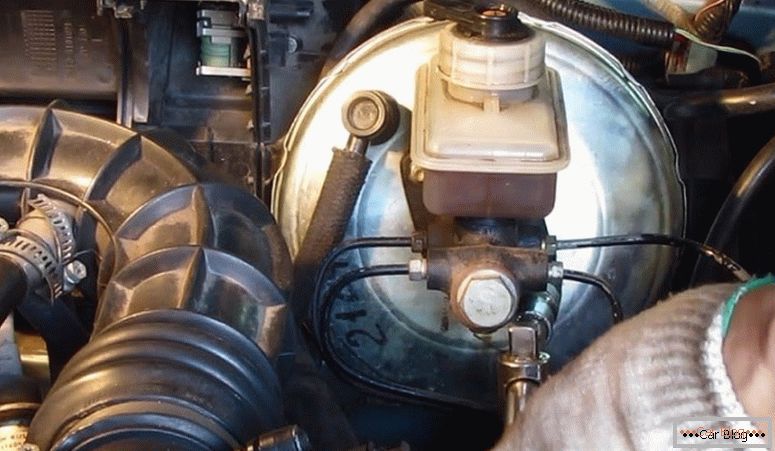
Installed new VUT
Instructions for replacing the vacuum brake booster
The replacement process of the vakuumnik is simple. Dismantling is the same as when removing the system for repair:
- Сначала отсоединяем stock от тормозной педали. То есть снимаем стопорную пластинку пальца, зацепив ее чем-нибудь острым. Теперь достаем палец и переходим под капот.
- Disconnect everything from the brake fluid level sensor to all wire pads.
- Disconnect the amplifier from the cylinder.
- Turn off the bracket nuts and remove the amplifier directly with him. If it is difficult to remove the nuts, you can use WD-40 liquid.
- We disconnect by unscrewing two nuts.
- Now we fix the new amplifier to the bracket and assemble it in the reverse order.

